
Rod and Reel – Reverse Engineering
STORY
Fishing has always been a hobby of mines so when I had the chance to create a personal project to better understand plastic part design using SolidWorks I chose my fishing rod and reel as an example to reverse engineer.
The project progressed through the following stages. 3D Laser Scanning on the rod handle and portions of the reel. A sketch picture-to-CAD of the reel frame. Some hand measurement of the rod and reel. CAD draft analysis of plastic rod grip. Lastly the final 3D modeling of the rod and reel combo to be rendered in KeyShot.

CHALLENGE
The aim of this project was to reproduce an injection molded plastic part using advance surface modeling techniques in SolidWorks while maintaining part accuracy.
OUTCOME
A professional 3D CAD file that can be used for prototyping, quoting, manufacturing, or product renderings for marketing purposes.
3D Scanning
In order to successfully reverse engineer the rod and reel, 3D laser scanning was the preferred method to capture the areas of complex geometry as it was either difficult to measure or model by hand accurately. In this case it was the grip handle on the rod and the frame on the reel.

3D Scanned Data of reel using Nextengine 3D Scanner along with Geomagic Design X for Reverse Engineering to capture complex surfaces (frame).

3D Scanned Data of rod using Nextengine 3D Scanner along with Geomagic Design X for Reverse Engineering to capture complex surfaces (grip).
CAD Development
The scan data is then imported into SolidWorks to start the reverse engineering process using advance surface modeling to construct each face. After the model is complete draft analysis was performed to make sure that a clean parting line for plastic mold injection could be established.

Imported Scanned data over SolidWorks CAD data.

SolidWorks Draft Analysis showing 2 deg at the parting line for tooling.

SolidWorks - Fishing Reel CAD model.

SolidWorks - Fishing Rod and Reel combo. Colors we used to separate materials when imported into KeyShot scene.
Bill of Materials (BOM)
Exploded assembly drawings and detailed Bill of Materials (BOM) were used throughout the prototyping process as a way to organize parts that were custom built or off the shelf components

2D Documentation - Exploded View and Bill of Materials (BOM) illustration.
Production Drawing

Production Drawing - Rod critical dimension for first article inspection.
Product Renderings
Product visuals help the product development process in myriad ways. They help “sell” ideas or concepts long before they exist in physical form and can shorten the time to market way before the product is actually release. Examples would be for presentations, marketing and advertising collateral, web and social media content, print media collateral.

KeyShot Scene 1 - Before materials were applied scene.

KeyShot Scene 1 - After materials were applied scene.
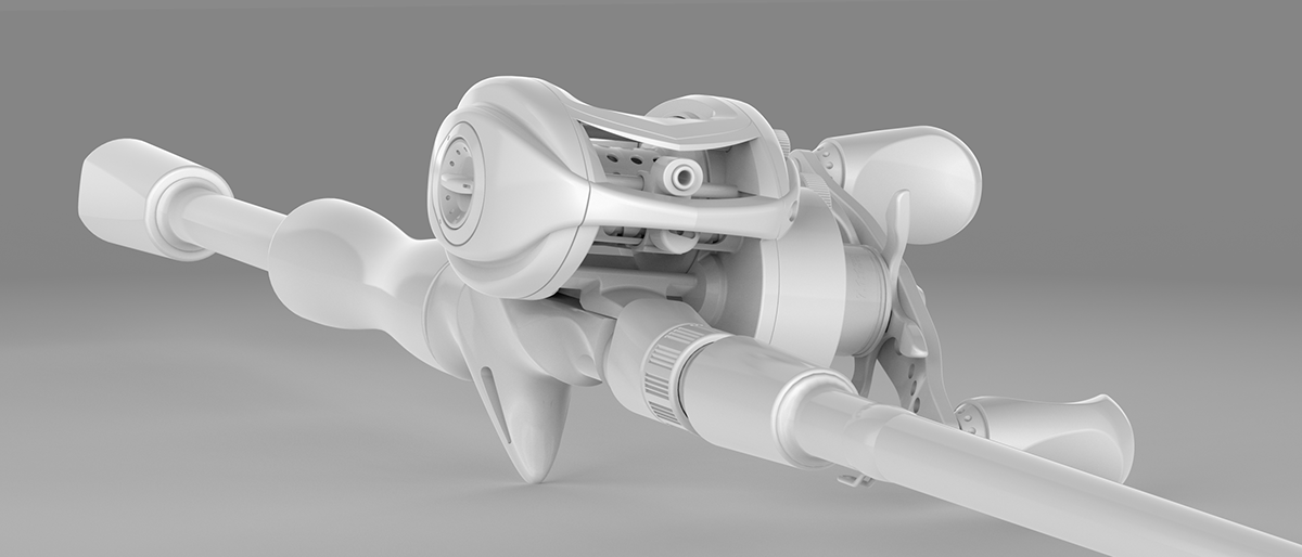
KeyShot Scene 2 - Before materials were applied scene.

KeyShot Scene 2 - After materials were applied scene.
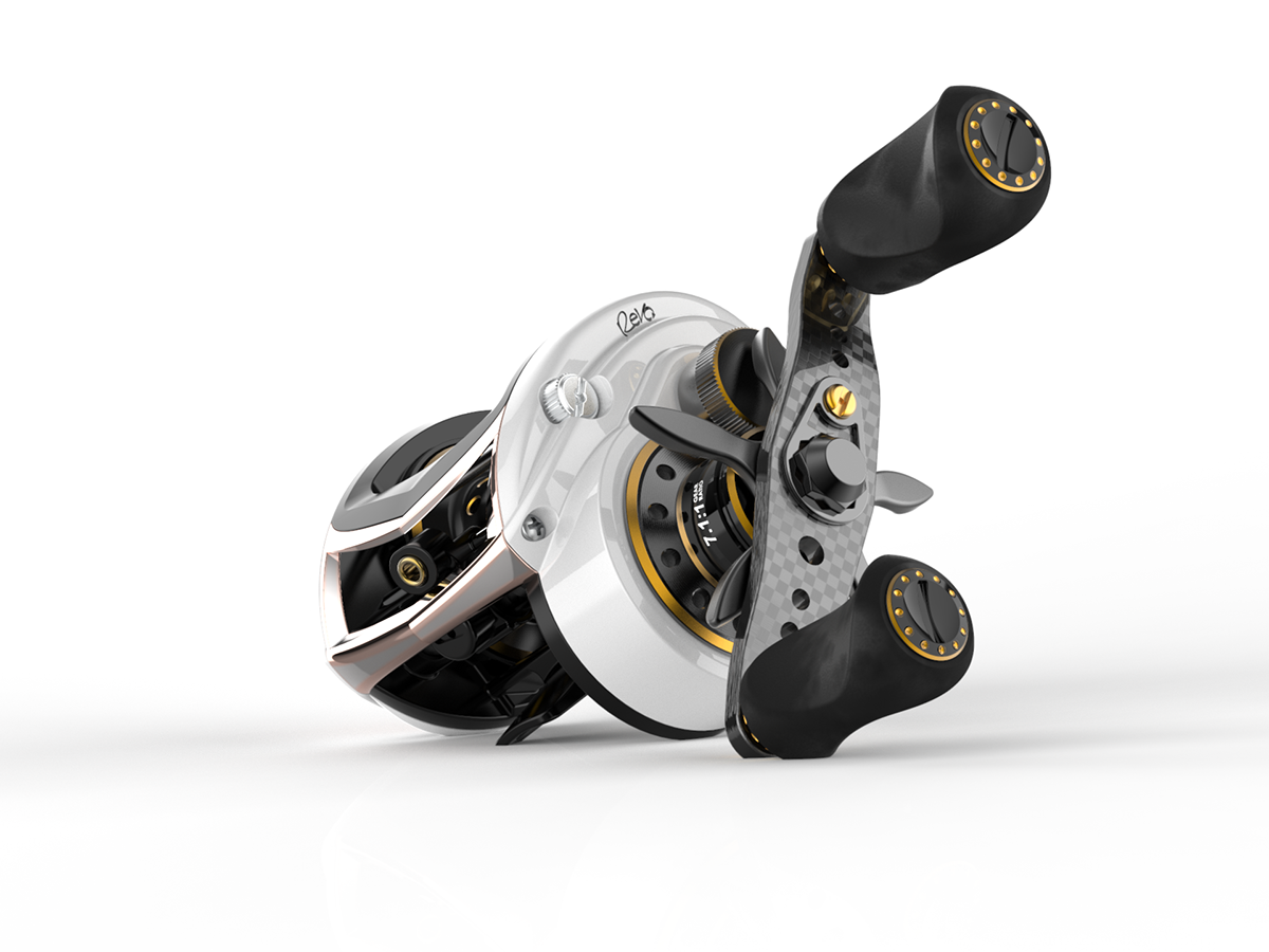
KeyShot Rendering - Feature hero shot example.

KeyShot Rendering - Color options example.
Please appreciate this project if you find this helpful. Thanks!
To learn more please visit www.rathasochenda.com


